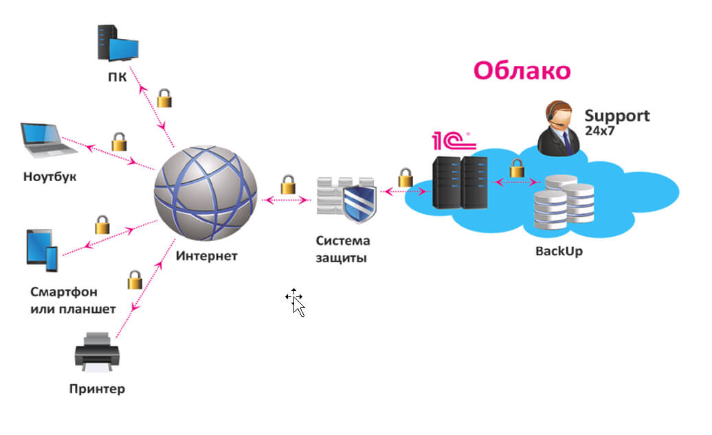
Выделенный сервер — это мощное и эффективное решение для бизнеса и крупных проектов в Интернете, требующих высокой производительности, безопасности и стабильности. Рассмотрим подробнее, что такое выделенный сервер Windows, его преимущества и возможные сценарии использования. Что такое выделенный сервер Windows? Выделенный сервер Windows — это физический сервер, который хостинг-провайдер предоставляет в аренду одному клиенту. Это обеспечивает […]
Аренда сервера для 1С: экономически выгодное и эффективное решение для вашего бизнеса
Экономия на покупку и содержание сервера в офисе: основные преимущества аренды Владение собственным сервером для работы с программой 1С может быть дорогим и трудоемким процессом. При этом https://rackstore.ru/arenda-servera-1c.html предоставляет целый ряд преимуществ, среди которых — снижение капитальных затрат. Вы больше не должны беспокоиться о затратах на приобретение оборудования, размещение его в офисе, обслуживание и обновление. […]
Проверка на антиплагиат на сайте: зачем и как это сделать
Актуальность проверки на антиплагиат Плагиат – это кража чужого интеллектуального труда. В современном мире, когда доступ к информации стал простым и быстрым, проблема плагиата стала особенно актуальной. Все больше людей сталкиваются с необходимостью проверки текстов на уникальность. Особенно это касается студентов, преподавателей, журналистов и авторов профессиональных текстов. В этой статье мы поговорим о том, почему […]
Купить прокси — эффективный инструмент для защиты данных и обхода блокировок
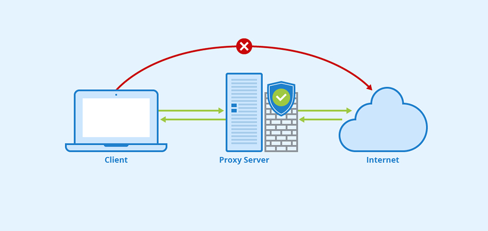
Какие преимущества предоставляют приватные Socks5 & HTTPs прокси Интернет-безопасность: защита личной информации При подключении к общедоступной сети Интернет необходимо обеспечить защиту личных данных. Приватные Socks5 & HTTPs прокси позволяют обезопасить себя от возможных утечек информации, таких как пароли, личные данные, финансовая информация. Они действуют как посредник между пользователем и внешним ресурсом, обеспечивая конфиденциальность и безопасность во […]
Ремонт техники Apple: подробное руководство
Введение: Продукты Apple известны своим элегантным дизайном, передовыми технологиями и надежной работой. Однако, как и любое другое электронное устройство, оборудование Apple иногда может столкнуться с проблемами, требующими ремонта. Целью этой статьи является предоставление подробного руководства по ремонту оборудования Apple, описание распространенных проблем и описание шагов, которые необходимо предпринять, чтобы обратиться за профессиональной помощью или выполнить […]
Исследование мира обменников криптовалют: раскрытие возможностей цифровых активов
Введение: Криптовалюта произвела революцию в финансовой сфере, а вместе с ней возникла необходимость в эффективных и безопасных платформах для обмена этими цифровыми активами. Обменники криптовалют стали жизненно важными игроками в отрасли, позволяя пользователям покупать, продавать и торговать различными криптовалютами. В этой статье мы углубляемся в мир обменников криптовалют, изучаем их функции, преимущества и особенности, которые […]
Откройте для себя прелесть речных круизов в России
Введение: Россия, известная своей богатой историей, потрясающими пейзажами и яркой культурой, предлагает путешественникам уникальную возможность исследовать свои сокровища во время речных круизов. Отправляясь в речное путешествие по России, вы откроете для себя целый ряд впечатлений, погружая вас в разнообразные регионы страны и впечатляющую природную красоту. Давайте окунемся в чарующий мир речных круизов по России, подробности […]
Личный кабинет в Совкомбанк Халва: регистрация, вход, получение карты рассрочки
Как оформить карту Дополнительная регистрация для доступа к личному кабинету карты «Халва» не предусмотрена. Авторизация происходит по номеру мобильного телефона и проверочного кода, который приходит через SMS. И раз уж дополнительные действия ненужны, значит, пора разобраться в том, как оформить новинку от «Совкомбанка», не выходя из дома: Еще до посещения главной страницы сервиса стоит разобраться […]
Как зарегистрироваться в Яндекс Деньги, бесплатная регистрация кошелька сейчас
Яндекс. Деньги – популярный сервис от российской компании «Яндекс». Позволяет совершать денежные платежи онлайн, а также моментально проводить различные платёжные операции. Сейчас является основным конкурентом международной системе расчёта Webmoney. Из этой статьи вы узнаете, как зарегистрироваться в системе Яндекс Деньги бесплатно. Регистрация Чтобы получить полноценный доступ ко всем функциям, предоставляемым сервисом Яндекс Деньги, пользователю необходимо […]
Личный кабинет в интернет-банке Генбанк: онлайн вход и регистрация на сайте
ГенБанк, как и многие другие финансовые организации, предоставляет услуги онлайн-банкинга для своих клиентов. Вход в личный кабинет Генбанка осуществляется через браузер и мобильные приложения, для юридических лиц потребуется загрузить на компьютер приложение bifit Signer, генерирующее электронную подпись клиента. Функционал Функционал личного кабинета содержит все стандартные функции, такие как: Внешние и внутренние переводы средств; Проверка оставшегося […]


